
A stable wired network connection depends not only on routers, switches, and network equipment but also on the quality of the Ethernet cable itself. In home renovations, office network deployments, or DIY networking projects, there are many situations where a pre-made cable is not the ideal solution. Creating a customized Ethernet cable with the correct RJ45 wiring method can provide better cable management, easier installation, and reliable network performance.
Whether replacing a damaged connector, shortening an oversized cable, or making a cable with a specific length, learning how to wire an Ethernet cable is a valuable skill. The key is understanding the wiring standard and following the correct crimping process.
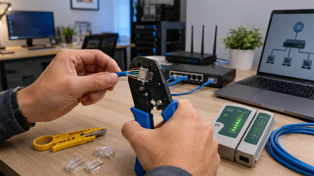
Understanding RJ45 Ethernet Cable Wiring Standards
RJ45 is the most common connector used for Ethernet network cables. Inside a standard Ethernet cable are four twisted wire pairs, containing eight individual wires. These wires must be arranged in a specific order before being inserted into the RJ45 connector.
There are two recognized Ethernet wiring standards:
T568A
T568B
The main difference between them is the position of the orange and green wire pairs. Both standards provide the same electrical performance when properly installed, but T568B has become the more commonly used wiring method in many residential and commercial network installations.
For most home networks, office networks, and Ethernet patch cables, using T568B on both ends is the recommended approach. This creates a standard straight-through Ethernet cable that works with computers, routers, switches, access points, and other network devices.
T568B Ethernet Cable Color Order
The T568B wiring sequence from Pin 1 to Pin 8 is:
Pin | Wire Color |
Pin 1 | White Orange |
Pin 2 | Orange |
Pin 3 | White Green |
Pin 4 | Blue |
Pin 5 | White Blue |
Pin 6 | Green |
Pin 7 | White Brown |
Pin 8 | Brown |
A simple memory method is:
White Orange → Orange → White Green → Blue → White Blue → Green → White Brown → Brown
This color arrangement must be identical on both ends of the cable when making a standard straight-through Ethernet cable. Mixing T568A on one end and T568B on the other creates a crossover cable, which is rarely required in modern networks because most equipment supports Auto-MDI/MDIX.
Tools Required for Ethernet Cable Crimping
Before starting the wiring process, prepare the following tools:
1. Ethernet Cable
Common choices include:
Cat5e cable: Suitable for basic Gigabit networks
Cat6 cable: Recommended for higher-performance home and office networks
Cat6a/Cat7 cable: Used for higher bandwidth applications
2. RJ45 Connectors
Choose connectors that match the cable category. For example, Cat6 cables usually require Cat6-compatible RJ45 plugs.
3. RJ45 Crimping Tool
A crimping tool is used to secure the connector onto the cable. It pushes the metal contacts inside the RJ45 plug into the cable conductors, creating a reliable electrical connection.
4. Cable Stripper
A stripper removes the outer jacket without damaging the internal wires.
5. Cable Tester
A cable tester is highly recommended. It can quickly identify wiring errors, missing connections, or incorrect pin sequences.
Step-by-Step Guide: How to Wire an Ethernet Cable
Step 1: Strip the Cable Jacket
First, remove approximately 2–3 cm of the outer cable jacket to expose the four twisted wire pairs.
Be careful not to damage the internal wires. The twisted structure helps reduce signal interference, so avoid removing more insulation than necessary.
Step 2: Arrange Wires According to T568B
Separate the four twisted pairs and arrange the eight wires in the correct T568B order:
White Orange → Orange → White Green → Blue → White Blue → Green → White Brown → Brown
Straighten each wire as much as possible. Uneven or twisted wires can make insertion into the RJ45 connector difficult and may cause poor contact.
Step 3: Cut the Wires Evenly
After arranging the wires, hold them tightly and cut all eight wires to the same length.
The wire ends should form a flat line so that every conductor reaches the metal contacts inside the RJ45 connector.
Uneven wire lengths are one of the most common causes of failed Ethernet cable termination.
Step 4: Insert Wires into the RJ45 Connector
Insert the wires into the RJ45 plug while maintaining the correct sequence.
Before crimping, check:
All eight wires reach the front of the connector
The color order is correct
The cable jacket enters the connector properly
The cable jacket should be held by the RJ45 connector after crimping to improve mechanical strength.
Step 5: Crimp the Connector
Place the RJ45 connector into the crimping tool and press firmly.
The metal contacts inside the connector will penetrate the wire insulation and establish electrical connections.
A proper crimp should have:
Secure connector attachment
Correct wire alignment
No loose movement between cable and plug
Step 6: Test the Ethernet Cable
After completing both ends, use a network cable tester.
A correctly wired cable should show:
1 → 2 → 3 → 4 → 5 → 6 → 7 → 8
All eight conductors should connect correctly.
Testing is especially important before installing cables inside walls, ceilings, or cable channels because troubleshooting later can be much more difficult.
Common Ethernet Cable Wiring Mistakes
1. Incorrect Wire Sequence
Even one misplaced wire can prevent network communication or reduce performance.
Always double-check the T568B color order before crimping.
2. Different Standards on Both Ends
Using T568B on one end and T568A on the other creates a crossover cable.
For normal network connections, keep both ends identical.
3. Excessive Untwisting
Ethernet cables rely on twisted pairs to reduce interference. Untwisting too much cable near the connector can affect signal quality, especially for higher-speed networks.
4. Skipping Cable Testing
A cable may look correct but still have hidden problems such as:
Open circuits
Short circuits
Incorrect pin order
Poor contact
A simple cable tester can prevent unnecessary troubleshooting.
Tips for Creating Reliable Ethernet Cables
For better network performance:
Use high-quality Cat5e or Cat6 cables
Match connectors with cable specifications
Keep cable bends gentle
Maintain wire pair twisting as close as possible to the connector
Test every finished cable
For home users, a properly made Cat6 T568B cable can easily support modern applications such as online gaming, 4K streaming, smart home devices, and high-speed broadband connections.
Tag:Ethernet Cable